How to improve the transformer quality
1. Improve the design requirements for the ability of the transformer to withstand short-circuit currents.
The symmetrical short-circuit current (thermally stable current) that the distribution transformer bears should be considered as 1.1 times the current in the most unfavorable three-phase short-circuit condition. The peak value of the short-circuit current (dynamic stable current) that should be withheld should be as short-circuit occurs at the terminal voltage passing zero The instantaneous (maximum peak current coefficient) is considered at 1.05 times the current. This calculates the short-circuit mechanical force that the transformer needs to withstand, and calculates the short-circuit mechanical force that the transformer’s structural components (windings, cores, insulation, clamps, fuel tanks, etc.) should withstand, and maintains a sufficient margin during design.
Note: The most unsuccessful items for spot inspection are three items: short circuit resistance, temperature rise and load loss. The solution to the three types of problems is the key to improving product quality.

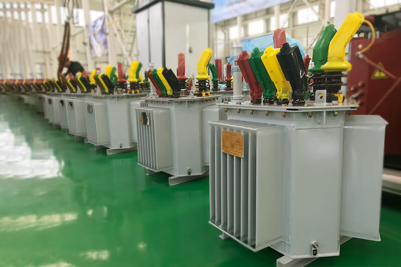
2. Optimize the heat dissipation design of oil-immersed transformer.
Ensure that the design temperature rise of the winding and oil surface is at least 5K lower than the contract value. There is a certain margin for the selection and specification of the heat sink or corrugated sheet. When designing the oil duct, the position of the oil duct should be reasonably arranged, the number of stays should be set, the width of the oil duct should be increased, and the oil stagnation area existing in the body should be reduced. The influence of parameters such as short-circuit resistance and insulation should also be considered in the heat dissipation design.
Note: The oil tank volume of the transformer, the coil’s electrical density, the way and number of insulation banding, and the heat dissipation area of the radiator are the main factors affecting the temperature rise.
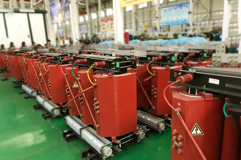
3. Optimize dry-type transformer design.
In order to improve the short-circuit resistance of dry-type transformers, the effective support between the low-voltage coil and the iron core should be no less than 4 points. In order to control the dry discharge partial discharge, the field strength between layers is designed not to exceed 2000V / mm.
4. Optimize the design of amorphous alloy core transformer.

Under the condition that the loss meets the design requirements, the core should preferentially choose a strip with high saturation magnetic induction strength. An epoxy glass fiber tube is added as a supporting structure between the low-voltage coil and the core of the amorphous alloy core transformer to increase the strength of the coil structure and reduce the extrusion of the amorphous alloy core when the coil is deformed by force. When designing, avoid that the difference between the long axis and the short axis of the low voltage winding is too large.
Note: The closer the amorphous alloy core transformer coil is to a non-circular shape, the easier it is to deform during the test and the easier it is to squeeze the amorphous core.
5. Strictly follow the design of the transformer to obtain the type test report for production.
Regardless of whether the manufacturer’s own design drawings or imported design drawings are used, trial production and type test reports should be obtained before mass production. The final product produced shall be consistent with the sample drawings and technical parameters of the obtained type test report, otherwise the calculation shall be checked again.
Note: For newly introduced design drawings, it is difficult for the manufacturer to master its process control requirements, and trial production should be carried out first.